Open circuit voltage can vary depending on your solar panel but the readings we are usually looking for are in the range of 15 to 23v.
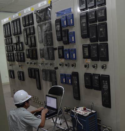
Protective relaying testing for solar panels.
The relays rest on the desktop either end of the test set.
Tecquipment supply each relay in rugged portable enclosures.
Solar panel modules go through stringent testing prior to being introduced to the market.
As most solar panels are 12 volts the solar panel test methods are basically the same.
The relaying equipment is aided in this task by instrument transformers that sense power conditions and circuit breakers that are capable of disconnecting the faulty element when called upon.
These contacts in turns close and complete the circuit breaker trip coil circuit hence make the circuit breaker tripped for disconnecting the faulty portion of the electrical circuit from rest of the healthy circuit.
You will want to ensure that you place the positive to positive and negative to negative when attaching your multimeter to the connection on the back of your solar panel.
A transmission line on the upper panel of the test set allows students to set up distance protection and parallel feeder tests.
The solar pv modules are subjected to a solar radiation of 1000 w m a module temperature of 25 c and an air mass coefficient of 1 5.
Protective relays are used extensively across the power system to remove any element from service that suffers a short circuit starts to operate abnormally or poses a risk to the operation of the system.
Under over current protects against current fluctuations by tripping when the current level goes outside of the current limits.
Solar protection relay functions.
Solar panels and generation by the strings of short circuit currents with values very near to those produced in normal conditions the presence of voltage as high as 300 600 v d c.
Simply touch the solar panel leads with the multi meter probes matching their corresponding polarity red to red black to black.
How to test a 12 volt solar panel vs other voltages.
And beyond requires a very careful assessment of the protection and isolating devices which must be able to suppress direct fault currents under high voltages.
They enable the evaluation and comparison of different solar panel types by determining current voltage and power of solar pv panels under comparable test conditions.
Rate of change of frequency rocof protects against frequency instability when the.
Some exceptions may apply based on panel type.
Under over voltage protects against voltage fluctuations that can lead to things such as insulation damage or inefficient performance.
These tests which can last for multiple months are critical to determining the quality and performance of panels under particular environmental stresses as well as confirming they meet mandated safety requirements.
The user programs the relays either directly or using software.